
Learning to use a multimeter is an essential skill for every electronics student, opening doors to practical understanding of circuits and electrical systems.
🔌 Why Every Student Needs to Master Multimeter Basics
The multimeter stands as one of the most fundamental tools in electronics education. Whether you’re pursuing electrical engineering, robotics, or simply exploring DIY electronics projects, understanding how to properly use this versatile instrument transforms abstract electrical concepts into tangible measurements you can see and verify.
Many students feel intimidated when first encountering a multimeter’s array of settings, buttons, and ports. However, once you understand the basic principles and techniques, this powerful diagnostic tool becomes your trusted companion in troubleshooting circuits, verifying component values, and ensuring electrical safety.
Modern digital multimeters have become increasingly affordable and user-friendly, making them accessible to students at all levels. From checking battery voltage to measuring resistance in resistors, the multimeter provides immediate feedback that reinforces theoretical knowledge learned in classrooms.
Understanding Your Multimeter: The Essential Components
Before diving into measurement techniques, familiarizing yourself with the multimeter’s anatomy is crucial. Every multimeter, whether analog or digital, shares common features that serve specific purposes in electrical measurements.
The Display Screen: Your Window to Electrical Properties
Digital multimeters feature an LCD display that shows numerical readings, making measurements precise and easy to interpret. Most displays show three to four digits, with some models offering additional symbols indicating measurement mode, battery status, and warning indicators.
The display provides real-time feedback, allowing you to observe changes instantly as you probe different points in a circuit. Understanding what these numbers represent in context is fundamental to accurate measurement interpretation.
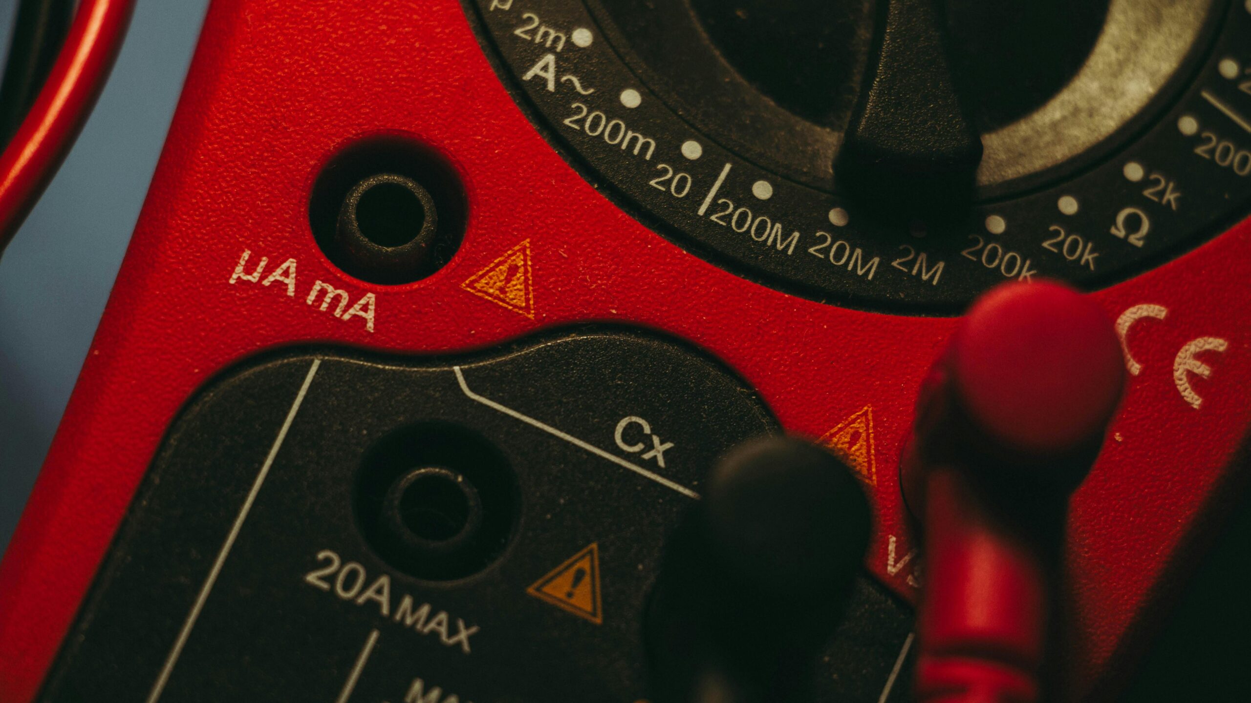
Selection Dial and Measurement Modes
The rotary selector dial, positioned centrally on most multimeters, allows you to choose between different measurement functions. Common settings include voltage (AC and DC), current (AC and DC), resistance, continuity, and sometimes additional features like capacitance or frequency.
Each position on the dial corresponds to a specific measurement type and range. Selecting the appropriate setting before connecting your probes prevents damage to both the multimeter and the circuit being tested.
Input Ports and Test Probes
Most multimeters feature three or four input jacks. The COM (common) port serves as the reference point for all measurements, while other ports accommodate different measurement types. The red probe typically connects to the positive terminal, and the black probe to COM.
High-quality test probes with sharp tips and insulated handles ensure both accurate contact and user safety. Understanding which port to use for each measurement type prevents incorrect readings and potential equipment damage.
⚡ Measuring Voltage: Your First Essential Skill
Voltage measurement represents the most common multimeter application and serves as an excellent starting point for beginners. Understanding the difference between AC and DC voltage is fundamental before proceeding.
Direct Current (DC) Voltage Measurements
DC voltage measurements apply to batteries, power supplies, and electronic circuits. To measure DC voltage correctly, set your multimeter dial to the DC voltage symbol (typically V with a straight line or V with three dots).
Connect the black probe to COM and the red probe to the voltage input jack. Touch the black probe to the circuit’s ground or negative terminal, and the red probe to the positive point you wish to measure. The display shows the voltage difference between these two points.
Starting with a higher voltage range and working downward ensures you don’t overload the meter. Most modern auto-ranging multimeters handle this automatically, but understanding manual ranging builds better technical intuition.
Alternating Current (AC) Voltage Testing
AC voltage measurements require extra caution since they often involve higher voltages from wall outlets and mains power. Set your dial to AC voltage mode (V with a wavy line or V~).
When measuring AC voltage, probe polarity matters less since the current alternates direction. However, maintaining consistent measurement practices helps prevent errors and ensures safety. Never measure AC voltage in circuits carrying more than your multimeter’s rated capacity.
🔍 Resistance Measurements: Testing Components
Measuring resistance helps verify component values, identify broken connections, and troubleshoot circuit problems. This measurement type requires understanding some important preparatory steps.
Preparing for Accurate Resistance Readings
Before measuring resistance, always disconnect power from the circuit. Resistance measurements involve the multimeter sending a small current through the component, and external voltage sources interfere with accurate readings.
For components in circuits, best practice involves removing at least one lead from the circuit board. This isolation prevents parallel paths through other components from affecting your measurement.
Reading Resistor Values and Verification
Select the resistance (Ω) setting on your multimeter. Touch both probes to the resistor leads, noting that polarity doesn’t matter for resistance measurements. The display shows the resistance value in ohms, kilohms, or megohms depending on the magnitude.
Comparing measured values with color code markings or component datasheets confirms component quality. Resistors typically have 5-10% tolerance, so slight variations from nominal values are normal.
Testing Continuity: Finding Breaks and Shorts ⚡
Continuity testing quickly identifies open circuits, broken wires, and unintended connections. This function proves invaluable when troubleshooting non-functional circuits or verifying PCB traces.
Set your multimeter to continuity mode, usually indicated by a diode symbol with sound waves. When the probes contact two electrically connected points, the meter emits an audible beep, providing instant feedback without needing to watch the display.
This feature streamlines testing cables, switches, fuses, and PCB connections. The audio feedback lets you focus on probe placement rather than constantly checking the screen, making troubleshooting faster and more efficient.
📊 Current Measurements: Advanced but Accessible
Measuring current differs fundamentally from voltage and resistance testing because the multimeter must become part of the circuit’s current path. This requirement demands extra care but provides crucial information about circuit operation.
Understanding Series Connection for Current
To measure current, you must break the circuit and insert the multimeter in series with the current flow. Connect the black probe to COM and the red probe to the appropriate current input jack (often labeled mA or A, depending on expected current magnitude).
Create a break point in your circuit where you want to measure current. Connect one probe to each side of the break, completing the circuit through the multimeter. The display shows the current flowing through that point.
Safety Considerations with Current Measurements
Current measurements pose the highest risk of multimeter damage. Always start with the highest current range available, and never measure current in voltage or resistance mode. Many multimeters include fuse protection, but prevention remains the best strategy.
Be particularly cautious with the current input jacks, as selecting the wrong range can blow internal fuses. Understanding your circuit’s expected current before measuring prevents costly mistakes.
🎯 Practical Measurement Techniques for Students
Developing proper measurement habits from the beginning establishes a foundation for more advanced electronics work. These techniques ensure accurate readings and prevent common student mistakes.
Proper Probe Contact and Handling
Firm, stable contact between probes and measurement points is essential for accurate readings. Unstable connections cause fluctuating readings and can lead to incorrect conclusions about circuit behavior.
Hold probes by their insulated handles, never touching the metal tips during measurements. This practice ensures personal safety and prevents your body resistance from affecting measurements, particularly important with high-impedance circuits.
Recording and Documenting Measurements
Maintaining a measurement log develops professional habits and provides reference data for lab reports and troubleshooting. Record the measurement type, range setting, probe positions, and observed values for each test.
Photographs or sketches of probe placement help recreate measurements later and communicate your testing methodology to instructors or collaborators. This documentation proves invaluable when analyzing complex circuits or explaining your troubleshooting process.
Common Student Mistakes and How to Avoid Them
Learning from common errors accelerates your multimeter mastery. Understanding these pitfalls before encountering them saves time, prevents equipment damage, and builds confidence in your measurement skills.
Wrong Mode Selection Consequences
Attempting to measure voltage in current mode or resistance in voltage mode represents the most frequent student error. This mistake can damage the multimeter, blow fuses, or create dangerous situations.
Always verify your dial setting before connecting probes. Develop a pre-measurement checklist: identify what you’re measuring, select the appropriate mode, choose the correct range, and verify probe placement in the right ports.
Measuring Resistance in Powered Circuits
Attempting resistance measurements without disconnecting power yields inaccurate readings and risks damaging your multimeter. The circuit’s active components and voltage sources interfere with the multimeter’s small test current.
Always power down and discharge capacitors before resistance measurements. This simple step prevents errors and protects both your instrument and the circuit under test.
🛠️ Maintaining Your Multimeter for Reliable Results
Proper maintenance extends your multimeter’s lifespan and ensures measurement accuracy. Students often overlook these simple care practices, leading to unreliable readings and premature equipment failure.
Regularly check and replace the battery to prevent unexpected power loss during critical measurements. Low battery voltage can cause inaccurate readings, particularly in resistance and continuity modes.
Inspect test probe cables for fraying, damage, or broken connections. Damaged probes compromise measurement accuracy and pose safety risks. Replace worn probes immediately rather than attempting repairs that might fail at critical moments.
Store your multimeter in a protective case when not in use, preventing dust accumulation and physical damage. Avoid exposing it to extreme temperatures or moisture, which can damage internal electronics and display components.
Building Confidence Through Practice Projects 📚
Theoretical knowledge transforms into practical skill through hands-on practice. These beginner-friendly projects help students develop multimeter proficiency while reinforcing electrical concepts.
Battery Testing and Power Supply Verification
Start by measuring voltages of various batteries—AA, AAA, 9V, and button cells. Compare new and used batteries to understand voltage degradation. This simple exercise builds comfort with probe placement and reading interpretation.
Progress to testing wall adapters and bench power supplies, verifying their output voltages match rated specifications. This practice introduces AC voltage measurement and develops awareness of voltage regulation quality.
Component Identification and Verification
Gather a collection of resistors and use your multimeter to verify their values against color codes. Measure capacitance if your multimeter includes this function, comparing results with component markings.
Test diodes using the diode test mode, observing forward and reverse bias characteristics. This exercise introduces semiconductor testing concepts while building measurement confidence.
Simple Circuit Troubleshooting Exercises
Create intentional faults in simple circuits—open connections, reversed components, or incorrect values. Practice systematic troubleshooting using voltage, resistance, and continuity measurements to identify problems.
These exercises develop the logical troubleshooting methodology essential for more complex projects. Document your process, noting which measurements revealed each fault and why particular tests were effective.
⚡ Advanced Features Worth Exploring
Once comfortable with basic measurements, exploring advanced multimeter features expands your diagnostic capabilities. Understanding these functions prepares you for more sophisticated electronics projects.
Diode and Transistor Testing
Many multimeters include dedicated diode test modes that measure forward voltage drop, helping identify component polarity and functionality. Some models offer transistor testing sockets that determine gain (hFE) values.
These features prove invaluable when sorting components or verifying semiconductor operation before circuit installation. Understanding semiconductor testing fundamentals broadens your electronics troubleshooting capabilities.
Capacitance and Frequency Measurements
Higher-end student multimeters often include capacitance measurement ranges, allowing direct capacitor value verification. This feature eliminates guesswork when working with unmarked or questionable capacitors.
Frequency measurement capability enables testing oscillators, signal generators, and audio circuits. Understanding frequency characteristics deepens comprehension of AC circuit behavior and signal processing concepts.
Safety First: Essential Precautions for Student Users 🔐
Electrical safety cannot be overemphasized when learning multimeter techniques. Developing safe measurement habits from the beginning prevents accidents and builds professional practices.
Always verify circuit voltage levels before connecting your multimeter. Never assume circuits are de-energized—always test first. High-voltage circuits require specialized equipment and supervision beyond basic student multimeter capabilities.
Inspect your multimeter for damage before each use. Cracked cases, damaged probes, or exposed wiring make the instrument unsafe. Never use defective equipment; report damage to instructors or lab supervisors immediately.
Understand your multimeter’s Category (CAT) rating, which indicates its safety level for different voltage environments. Most student multimeters are CAT II rated, suitable for standard circuits but not for direct mains or industrial applications.
Integrating Multimeter Skills with Circuit Theory 🎓
The true power of multimeter mastery emerges when measurements reinforce theoretical understanding. Connecting practical measurements with classroom concepts transforms abstract formulas into concrete reality.
When studying Ohm’s Law, use your multimeter to measure voltage and resistance, then calculate expected current and verify with direct measurement. This experimental verification builds intuitive understanding beyond memorization.
Explore voltage divider circuits by measuring voltages across series resistors, comparing theoretical calculations with actual readings. Small discrepancies teach important lessons about component tolerance and real-world circuit behavior.
Practice Kirchhoff’s Laws by measuring voltages around complete loops and currents at circuit nodes. Verifying that voltage sums equal zero and currents balance at junctions transforms abstract rules into observable phenomena.
Choosing the Right Multimeter for Student Needs
While not necessary to master basic techniques, understanding multimeter selection criteria helps students make informed purchases or equipment requests. Different projects and educational levels require different capabilities.
Auto-ranging digital multimeters offer the easiest learning curve, automatically selecting appropriate measurement ranges. Manual-ranging models cost less and teach range selection skills but require more careful operation.
Resolution and accuracy specifications indicate measurement precision. Student work typically doesn’t require laboratory-grade precision, but understanding these specifications builds awareness of measurement limitations.
Safety features like fused inputs, overload protection, and CAT ratings deserve careful consideration. These features prevent damage from student errors and ensure safe operation in educational environments.
Resources for Continued Learning and Practice
Mastering multimeter techniques is an ongoing journey rather than a destination. Numerous resources support continued skill development beyond initial instruction.
Electronics textbooks typically include multimeter usage sections with measurement exercises. Online platforms offer video tutorials demonstrating proper techniques and troubleshooting strategies. Educational YouTube channels provide visual demonstrations particularly helpful for understanding probe placement and reading interpretation.
Electronics hobby forums and student communities offer spaces to ask questions, share experiences, and learn from others’ challenges. Engaging with these communities accelerates learning through collective knowledge and diverse perspectives.
Practice remains the most effective learning tool. Regular hands-on experience with different circuits, components, and measurement scenarios builds intuition and confidence that no amount of reading can replace.
Taking Your Skills to the Next Level
Solid multimeter fundamentals open pathways to more advanced diagnostic tools and techniques. Understanding basic measurements prepares students for oscilloscopes, function generators, and specialized test equipment encountered in advanced coursework.
The systematic troubleshooting methodology developed through multimeter practice applies broadly across electronics disciplines. Whether working with analog circuits, digital systems, or microcontroller projects, these fundamental measurement skills remain essential.
As you progress beyond basics, challenge yourself with increasingly complex circuits and measurement scenarios. Document your learning journey, noting insights gained and techniques discovered through hands-on practice.
Remember that every experienced electronics professional started exactly where you are now—learning to confidently hold probes, interpret readings, and understand what those numbers reveal about circuit behavior. Patience, practice, and persistence transform tentative beginners into confident practitioners who view the multimeter as an extension of their analytical thinking rather than an intimidating tool.