
Understanding how to protect your electronic circuits from overcurrent damage is essential for anyone working with electrical systems, whether you’re a hobbyist or professional engineer.
⚡ Why Circuit Protection Matters More Than You Think
Every electronic device you own relies on circuit protection to prevent catastrophic failure. From the smartphone in your pocket to the industrial machinery in manufacturing plants, fuses and current limiters stand as silent guardians against electrical disasters. When excessive current flows through a circuit, these protective devices act as the first line of defense, preventing fire hazards, equipment damage, and potential injury.
The cost of inadequate circuit protection extends far beyond replacing a burnt component. Electrical fires cause billions of dollars in property damage annually, and many of these incidents could have been prevented with proper overcurrent protection. Understanding the fundamentals of fuses and current limiters empowers you to design safer circuits and troubleshoot existing systems effectively.
🔧 The Science Behind Overcurrent Protection
Circuit protection devices work on a simple principle: they interrupt the flow of electricity when current exceeds safe levels. However, the mechanisms by which different devices achieve this protection vary significantly, each offering unique advantages for specific applications.
When electrical current flows through a conductor, it generates heat due to the conductor’s resistance. This relationship, described by Joule’s law, shows that heat production increases exponentially with current. Excessive current creates dangerous heat levels that can melt insulation, ignite flammable materials, or destroy sensitive electronic components.
Understanding Current Flow and Overload Conditions
Normal operating current represents the expected electrical flow during standard device operation. Overload conditions occur when current exceeds this nominal value but remains below short-circuit levels. Short circuits, by contrast, represent near-zero resistance paths that allow massive current surges, often hundreds or thousands of times the normal operating current.
Different protection strategies address these distinct scenarios. Slow-blow fuses tolerate brief current surges during motor startups, while fast-acting fuses respond immediately to short circuits. Understanding these distinctions helps you select appropriate protection for your specific application.
🎯 Fuses: Your First Defense Against Electrical Overload
Fuses represent the oldest and most widely used form of overcurrent protection. These simple yet effective devices contain a metal element that melts when current exceeds the fuse’s rated capacity, breaking the circuit and halting current flow.
The elegance of fuse design lies in its simplicity. A fusible element, typically made from tin, copper, silver, or zinc alloy, connects two terminals within an insulated housing. When normal current flows through this element, it remains stable. Excessive current generates heat that exceeds the element’s melting point, causing it to vaporize and create an air gap that stops current flow.
Types of Fuses and Their Applications
Fast-acting fuses, also called F-type fuses, respond almost instantaneously to overcurrent conditions. These fuses work best for protecting sensitive electronic equipment that cannot tolerate even brief current surges. Semiconductor circuits, measurement instruments, and control systems benefit from fast-acting protection.
Time-delay fuses, designated as T-type, accommodate temporary current surges without blowing unnecessarily. Motors, transformers, and capacitive loads create harmless inrush currents during startup that would destroy fast-acting fuses. Time-delay fuses ignore these brief surges while still protecting against sustained overloads.
Specialized fuses address unique protection requirements across various industries:
- High-voltage fuses protect power distribution systems and industrial equipment
- Automotive fuses safeguard vehicle electrical systems using blade-style designs
- SMD fuses provide protection for compact surface-mount circuit boards
- Resettable fuses, or polymeric positive temperature coefficient devices, automatically reset after cooling
- High-rupture capacity fuses interrupt massive fault currents in power systems
📊 Selecting the Right Fuse: Critical Parameters
Choosing appropriate fuses requires careful consideration of multiple electrical characteristics. Making informed selections prevents nuisance blowing while ensuring adequate protection against genuine fault conditions.
Voltage Rating Considerations
A fuse’s voltage rating indicates the maximum voltage it can safely interrupt. This rating must equal or exceed your circuit’s operating voltage. Using an under-rated fuse creates dangerous arc-over conditions where electricity jumps across the blown fuse gap, negating protection and creating fire hazards.
Voltage ratings account for the fuse’s ability to extinguish electrical arcs during interruption. Higher voltage circuits require larger physical gaps and specialized arc-quenching materials within the fuse body.
Current Rating and Load Calculations
Determining proper current ratings begins with calculating your circuit’s maximum operating current. Measure or calculate the total current draw of all connected loads, including startup surges for motors and inductive devices.
As a general guideline, select fuses rated at 125-150% of the circuit’s maximum continuous current. This margin prevents nuisance blowing from normal variations while providing protection against genuine overload conditions. Time-delay fuses may require different derating calculations based on expected surge characteristics.
Breaking Capacity Requirements
Breaking capacity, also called interrupting rating, specifies the maximum fault current a fuse can safely interrupt. This parameter becomes critical in systems connected to high-capacity power sources capable of delivering enormous short-circuit currents.
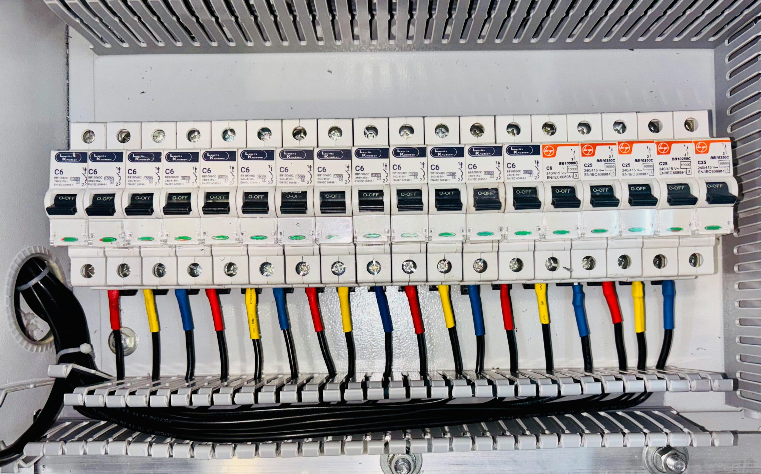
Residential circuits typically require fuses with 10,000-ampere interrupting ratings. Industrial applications may demand 100,000 amperes or higher. Using fuses with inadequate breaking capacity can result in explosive failure when attempting to interrupt high fault currents.
🛡️ Current Limiters: Advanced Protection Technology
Current limiters represent sophisticated alternatives to traditional fuses, offering resetability, precise control, and enhanced protection characteristics. These electronic devices actively monitor circuit current and respond dynamically to overcurrent conditions.
Unlike passive fuses that simply melt under excessive current, current limiters employ active circuitry to control and limit current flow. This fundamental difference enables features impossible with fuses, including adjustable trip points, controlled shutdown sequences, and automatic recovery.
Electronic Current Limiter Designs
Resistor-based current limiters use the voltage drop across a sense resistor to monitor circuit current. When this voltage exceeds a predetermined threshold, control circuitry activates a series pass element (typically a MOSFET or transistor) to limit current flow.
These devices offer excellent precision and fast response times measured in microseconds. They protect sensitive semiconductor devices from destruction during fault conditions while maintaining operation during brief overload events.
Magnetic current limiters exploit electromagnetic principles to achieve mechanical current interruption. When current exceeds safe levels, electromagnetic force moves a mechanical contact to break the circuit. This approach combines the resetability of electronic limiters with the simplicity of fuses.
Positive Temperature Coefficient (PTC) Devices
PTC devices, often called resettable fuses or polyfuses, represent a hybrid between fuses and current limiters. These polymer-based components exhibit a dramatic resistance increase when heated by excessive current.
At normal temperatures, PTCs conduct electricity with minimal resistance. Overcurrent generates heat that triggers a phase transition in the polymer matrix, increasing resistance by several orders of magnitude. This high-resistance state limits current to safe levels without completely interrupting the circuit.
Once the fault condition clears and the device cools, the PTC automatically returns to its low-resistance state, restoring normal operation. This automatic reset capability makes PTCs ideal for applications where manual fuse replacement proves inconvenient or impossible.
⚙️ Implementing Circuit Protection: Best Practices
Effective circuit protection requires more than selecting appropriate devices. Proper installation, coordination with other protective elements, and consideration of system-wide protection strategies ensure reliable operation.
Strategic Placement in Circuit Design
Protection devices belong as close as possible to the power source. This placement ensures that conductors carrying power to the protective device remain short, minimizing the length of unprotected wiring that could become a fire hazard during fault conditions.
Multi-stage protection strategies employ fuses or limiters at multiple points within complex systems. Primary protection at the main power input guards against major faults, while secondary protection on individual branches provides targeted defense for specific subsystems.
Coordination Between Protection Devices
When multiple protective devices exist in series, coordination ensures that the device closest to the fault operates first. This selectivity prevents upstream devices from interrupting power to healthy circuits when faults occur in isolated branches.
Achieving proper coordination requires careful selection of device characteristics. Downstream devices must operate faster than upstream devices for all possible fault current magnitudes. Time-current curves provided by manufacturers help engineers verify proper coordination.
🔍 Troubleshooting and Maintenance Strategies
Regular inspection and testing of circuit protection devices prevents unexpected failures and maintains system safety. Developing systematic troubleshooting approaches minimizes downtime when protection devices operate.
Identifying Why Fuses Blow
When fuses blow repeatedly, the underlying cause requires investigation before simple replacement. Genuine overload conditions demand either circuit modification to reduce load current or fuse upgrades to handle legitimate surge currents.
Short circuits present more serious concerns requiring immediate attention. Inspect wiring for damaged insulation, moisture infiltration, or mechanical damage. Test connected equipment for internal faults using insulation resistance meters or continuity checks.
Environmental factors sometimes cause mysterious fuse failures. Vibration can fatigue fuse elements, while temperature extremes affect fuse characteristics. Ensure fuses operate within their environmental specifications.
Testing and Validation Procedures
Periodic testing verifies that protection devices remain functional and properly rated. Visual inspection reveals physical damage, corrosion, or signs of overheating indicated by discoloration around fuse holders.
Continuity testing with a multimeter confirms that fuses conduct current properly. However, this test cannot verify that fuses will actually blow at their rated current. More sophisticated testing requires specialized equipment that safely generates controlled overcurrent conditions.
💡 Advanced Applications and Emerging Technologies
Circuit protection technology continues evolving to meet the demands of modern electronic systems. Smart protection devices incorporate digital communication, adaptive protection algorithms, and integration with building management systems.
Smart Fuses and Connected Protection
Next-generation protection devices communicate their status over digital networks, enabling remote monitoring and predictive maintenance. These intelligent systems track operating conditions, log trip events, and alert maintenance personnel before catastrophic failures occur.
Adaptive current limiters adjust their trip characteristics based on real-time analysis of circuit behavior. Machine learning algorithms distinguish between harmless transients and dangerous fault conditions with unprecedented accuracy.
Renewable Energy System Protection
Solar installations, wind turbines, and battery storage systems present unique protection challenges. DC circuits require specialized fuses designed to interrupt direct current, which maintains arcs more persistently than alternating current.
Bi-directional current flow in battery systems demands protection that operates regardless of current direction. Advanced current limiters with symmetric characteristics provide reliable protection for these emerging applications.
🎓 Building Your Circuit Protection Expertise
Mastering circuit protection requires combining theoretical knowledge with practical experience. Start with simple projects using basic fuses, then progress to more sophisticated applications incorporating electronic current limiters and coordinated protection schemes.
Study equipment schematics to understand how professional engineers implement protection strategies. Notice how industrial systems employ multiple layers of protection, each targeting specific failure modes. Analyze the voltage ratings, current capacities, and time-delay characteristics chosen for different applications.
Experimentation with properly rated components in controlled environments builds intuitive understanding of protection device behavior. Deliberately create overload conditions (safely!) to observe how different fuse types respond. Compare fast-acting versus time-delay characteristics under identical load conditions.
🚀 Taking Action: Protecting Your Projects Today
Armed with comprehensive knowledge of fuses and current limiters, you can now design and implement robust circuit protection for any application. Remember that protection devices represent insurance against costly failures and dangerous conditions.
Never compromise on circuit protection to save a few dollars. The cost of proper fuses or current limiters pales compared to replacing destroyed equipment or addressing fire damage. Professional installations must comply with electrical codes and standards that mandate appropriate protection.
Review existing projects and verify adequate protection. Calculate maximum currents, confirm voltage ratings, and ensure breaking capacity meets available fault current. Upgrade inadequate protection before failures occur rather than after.
The investment in understanding and implementing proper circuit protection pays dividends throughout your electronics journey. Whether you’re building hobby projects, maintaining industrial equipment, or designing commercial products, these principles ensure safety, reliability, and longevity for all your electrical systems.